Continue to Site

Welcome to MCAD Central

Join our MCAD Central community forums, the largest resource for MCAD (Mechanical Computer-Aided Design) professionals, including files, forums, jobs, articles, calendar, and more.

Modeling Tension Spring With Hook

scoutfai

New member
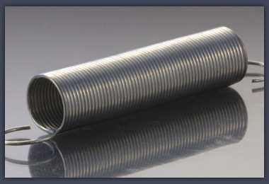
I have difficulty in modeling a tension spring with hook at both ends. The kind of spring I would like to model is as shown in the following image:
largeextensionspring.jpg

(The lowest is the type of spring I intend to model)

I have no difficulty to produce the helical part of such spring, i.e. the part where the spring touching itself at each revolution.
From the image, you can see that the hook is joint with the helical part at the circumference of the spring, not at the center. Obvious, draw the path of such hook is also not a problem. The problem comes when I intend to do a "fillet" of path between the sharp angle of the joint point of the hook and the helical path. I use numerous method, all end up error in swept boss/base. Can any one suggest how can such spring be modeled?
tension.jpg


Edited by: scoutfai
 
No one knows? I thought it is not so difficult, just that I do not know the trick....please help if you know the way to model it.
 
To get the sharp turn between the helical part and the hooked end I would do a simple 90degreee revolve at the end of the helical part and then sweep the hook shape.


I'll try and model it up now and post a pic.
 
I did it without the 90degree revolve and strightinto a sweep at the end of the helix. I did use ProE to do it but the principles are the same.


What way are you forming your helical part as this could be the problem area? Is the profile perpendicular to the helix?


I again cannot upload a pic to show you what i did.
smiley6.gif
 
The typical method to make a spring with hooks is:


- First create an helix.


- Nextsketchone hook.


- Next using a 3D sketch, use convert entities to bring both the helix and the hook into the sketch and join them with a spline. Use only2 points, one at the end of the helix, one at the beginning of the hook. Constrain the spline to be tangent to both the helix and the hook. Also make sure that the curvature of the spline is not less than the radius of the wire of your spring.


- Obviouly this has to be done at both ends.


- Finally, sweep using the 3D sketch as trajctory.


One could skip a step by making the hooks directly in the 3D sketch but I prefer to make it the way I described.
 
michael3130 said:
To get the sharp turn between the helical part and the hooked end I would do a simple 90degreee revolve at the end of the helical part and then sweep the hook shape.


I'll try and model it up now and post a pic.

Actually in the real spring as shown in my pictures above, the transition from the helix to the hook profile is not a 90 degree sharp turn. It is smoothly joint by a curve that connect the helix to the hook vertical line.
 
michael3130 said:
I did it without the 90degree revolve and strightinto a sweep at the end of the helix. I did use ProE to do it but the principles are the same.


What way are you forming your helical part as this could be the problem area? Is the profile perpendicular to the helix?


I again cannot upload a pic to show you what i did.
smiley6.gif
Although you did not use the "90 degree revolve" method, but I actually do not understand what you mean by a 90 degree revolve. Are you mean that from the end of the helix, directly draw a straight vertical line that acts as a hook? (if joint like this, then the point of joint will form a sharp angle)

I will try to post the pic of what I did to here.

Michael, you can upload your picture using printscreen to www.imageshack.com then post it here.
 
bjulien99 said:
The typical method to make a spring with hooks is:


- First create an helix.


- Nextsketchone hook.


- Next using a 3D sketch, use convert entities to bring both the helix and the hook into the sketch and join them with a spline. Use only2 points, one at the end of the helix, one at the beginning of the hook. Constrain the spline to be tangent to both the helix and the hook. Also make sure that the curvature of the spline is not less than the radius of the wire of your spring.


- Obviouly this has to be done at both ends.


- Finally, sweep using the 3D sketch as trajctory.


One could skip a step by making the hooks directly in the 3D sketch but I prefer to make it the way I described.

Your method is almost identical to mine. The only difference is I would prefer not to use spline to act as the "fillet". I will try to post the pictures of what I did in SolidWorks to illustrate my problem in detail.
 
At first, I draw a circle of 1 inch on the top plane.
1stb.jpg


Produce the helix with the parameters shown in the picture.
2nd.jpg


Sketch the hook on the right plane, I sketch the upper part first, then use mirror to produce the lower part.
3rdpmv.jpg


Then I create a plane at 1.40 inches away from the Front plane.
4thn.jpg


Sketch the fillet on this plane with radius shown. I do not draw two fillets because later on I have to use Project Curve. If got two fillets, the Project Curve unable to be done.
5thp.jpg


Then I project this fillet curve on to the circle profile of the helix.
6thm.jpg


Initiate a 3D sketch, convert all the shown entities (helix, upper hook vertical line, projected curve). In my point of view, this projected curve should be touching the helix as well as the hook vertical line.
7th.jpg


However, when I try to apply a Coincident relation on them, error occurs.
8th.jpg


Same thing happens with Tangent relation.
9thc.jpg


If I zoom in large enough, there is a gap visible. I don't know why got a gap. But apparently this is the reason why the projected can not be Coincident and Tangent.
10thc.jpg


Nevertheless, the projected curve does touches the hook vertical line. It is trim-able (shown with red color when I put Trim on it).
11th.jpg


With all this error, I am unable to continue with this method again.

There is people who suggested me to use spline to close the gap. Some suggest to directly use spline to make the fillet. I prefer to make a fillet that lies on the circumference surface of the helix, if I use spline, I am unable to be sure that this condition is met. Further more, if I use spline, I have no idea how can I ensure the upper fillet and the lower fillet are identical.

Hope you guys can give me some hints.
 
Scoutfai,


The reason your method won't work is because the path is not one continuous path, you have a loop embedded in there. The helix needs to flow smoothlyto the radius and then to the hook shape. Adding a fillt and leaving the joinging point between the helix and the hook path will not work.


Also, you can try breaking it up into pieces. It doesn't all have to be swept in one piece.


I realised about the 90degree bend when I started modelling it. Sometimes I write before I think....My wife says I talk before I think too!!!
smiley36.gif
 
michael3130 said:
Scoutfai,


The reason your method won't work is because the path is not one continuous path, you have a loop embedded in there. The helix needs to flow smoothlyto the radius and then to the hook shape. Adding a fillt and leaving the joinging point between the helix and the hook path will not work.


Also, you can try breaking it up into pieces. It doesn't all have to be swept in one piece.


I realised about the 90degree bend when I started modelling it. Sometimes I write before I think....My wife says I talk before I think too!!!
smiley36.gif

I believe the "loop" u mean is the the part in the following picture which I circled with green ellipse:
loop.jpg


Actually, my intention is that I want to trim out the red line and the extra helix curve so that the whole path does not have a 'loop' in it. However, I can only trim the red line, the extra helix curve is untrim-able because as I shown in previous post, there is a gap between the Projected Curve and the helix curve. I myself do not know why such gap exists. You got to zoom it till extremely large then only the gap is visible. I suggest you to follow my method and do it yourself, then you will realize what I mean.

The reason I will think that the Projected Curve should be coincident with the helix is because the curve that I used to project it was drawn to coincident with the helix at first.

Breaking out into pieces sound works and I believe it will. But I still curious about how to model such a spring with only one sweep operation.

I have to emphasize that I realize the use of Spline to join the hook and the helix as told by joelewinski is workable, but you got to drawn two splines separately to create the whole spring profile. How can one ensure that, the upper spline is identical to the lower spline? Mean I want their curvature, length, etc to be the same. Use mirror, perhaps?

Edited by: scoutfai
 
joelewinski said:

Joe L,

I found that this method is not doing thing in a complete correct manner.
It is fine to model a circular cross section spring using this method. But once u change the cross section profile to something else like a rectangular, u immediate notice that the hook twisted terribly at the point of joint with the helix. This is obviously not what we intended to have.

Is there any way can avoid such twist?
twist.jpg
 
scoutfai,


Yes, that's the bit i meant.


In the sweep feature, did you try altering the different settings? Play about with them until you get what you want to achieve. You could create the helix as one body, then the hook as one boby and loft between the 2 bodies to create the joining curve using guide curves to help. Although the sweep should work!!
 
Joe L,

I found that this method is not doing thing in a complete correct manner.
It is fine to model a circular cross section spring using this method. But once u change the cross section profile to something else like a rectangular, u immediate notice that the hook twisted terribly at the point of joint with the helix. This is obviously not what we intended to have.

Is there any way can avoid such twist?
twist.jpg

[/QUOTE]


To avoid the twist, you WOULD need a second path to "guide" the corners.


You said you wanted to model a spring as shown in the picture you posted. We're all trying to get you to that point. You shouldn't ask a question regarding specific information and then CHANGE YOUR PARAMETERS after we answer you saying that it doesn't work. IT DOES WORK! We're NOT mind readers. How were we to know you were going to do something different than what you asked for?


Boy, you try to help...
smiley7.gif


Ok, breath deep, slowly, slowly, . . . I'm better now.
 
Scoutfai,


THe reason why you cannot trim the helix with you filletis because it is not in the same plane as the fillet. When you created the fillet you where in a 2D sketch while the helix is a 3D curve.


Using the 3D sketch and the 2 points pline as in my previous post will work. To control the splines you can add a tangency constraint at both ends (hook and helix) and if you need more control you can add curvaturecontrol at both end of the spline also.


Here it is again:


1- make the helix.


2- make the hook, leave a gap between the linear part of the hook and the end of the helix to fit the spline that will join them.


3- in a 3D ketch convert the hook and the helix then make the 2 point spline. Assing tangency at both ends and for better control add radius dimensions at both ends (see the help for this). That way it is fully defined and it should repeat when you do the other end.


4- Do the sweep.
 
Scoutfai,


Joe is right. The pic is different from the initial pics you posted and Joe's answer is correct. Sweeping a circle roung the path would not have shown up a 'twist'
 
o yea...breath deep Joe, breath deep!!!
smiley36.gif


This site can take a lot of patience sometimes....though compared to being at home with 2 kids asking none stop quesitons it's quite relaxing!!!
smiley4.gif
 

Sponsor

Back
Top