Hi All,
I am new to Creo, but have done a bit of design (including stents) on Unigraphics/NX and Solidworks.
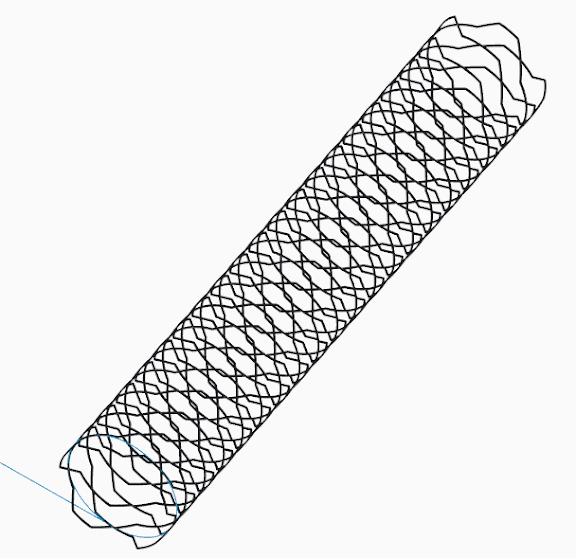
I am trying to model a stent (such as seen below) for export to Abaqus for FE and CFD.

I've tried a few different approaches, all that have ended up with me bashing my head on my desk from not understanding Creo's features.
My main strategy has been to start with a unit cell (or part of one), and tessellate it through the pattern function.
I start with a sketch of half a unit cell:

Then I sweep a rectangular cross section along the initial sketch. I then mirror the resulting solid twice to get the other half of the unit cell.

Then I make the unit into a pattern of 5x20 unit cells.
This is where things get messy (although this could be a symptom of doing something wrong earlier?). The cells don't quite align nicely - there is either overlap or underlap. I think the answer would be some kind of "unite" function, where the exterior surface would be saved from overlapping. There is a small 'lip' from where the unit cells don't quite align. I think I could fix this by either being more careful with the first sketch that the sweep was made with, or by adding rounds at this stage to "wipe" over them. When I try to add rounds at this point, the tool takes the edge as being for two separate solids.

I think the last step would be to use a Toroidal Bend to wrap the plane into a cylinder. This always fails when I try, and also fails with just the one unit cell. I am able to get it to roll with just a rectangular sheet, so I think I do know the tool well enough - I'm thinking its a problem with the solid I'm using?
Thanks for any help or advice!!
EDIT:
File is at http://www.filehosting.org/file/details/426385/stentpiecemeal.prt.9
Sorry I was having trouble uploading it here, I think it was unhappy with the .prt.9 extension
I am new to Creo, but have done a bit of design (including stents) on Unigraphics/NX and Solidworks.
I am trying to model a stent (such as seen below) for export to Abaqus for FE and CFD.
I've tried a few different approaches, all that have ended up with me bashing my head on my desk from not understanding Creo's features.
My main strategy has been to start with a unit cell (or part of one), and tessellate it through the pattern function.
I start with a sketch of half a unit cell:
Then I sweep a rectangular cross section along the initial sketch. I then mirror the resulting solid twice to get the other half of the unit cell.
Then I make the unit into a pattern of 5x20 unit cells.
This is where things get messy (although this could be a symptom of doing something wrong earlier?). The cells don't quite align nicely - there is either overlap or underlap. I think the answer would be some kind of "unite" function, where the exterior surface would be saved from overlapping. There is a small 'lip' from where the unit cells don't quite align. I think I could fix this by either being more careful with the first sketch that the sweep was made with, or by adding rounds at this stage to "wipe" over them. When I try to add rounds at this point, the tool takes the edge as being for two separate solids.
I think the last step would be to use a Toroidal Bend to wrap the plane into a cylinder. This always fails when I try, and also fails with just the one unit cell. I am able to get it to roll with just a rectangular sheet, so I think I do know the tool well enough - I'm thinking its a problem with the solid I'm using?
Thanks for any help or advice!!
EDIT:
File is at http://www.filehosting.org/file/details/426385/stentpiecemeal.prt.9
Sorry I was having trouble uploading it here, I think it was unhappy with the .prt.9 extension
Attachments

Last edited:
")